Project Background
This project was originally developed in 2021 during my freelancing work. It represents one of the initial versions of an RF Switch Matrix that I designed and implemented.
What is an RF Switch Matrix?
If you’re unfamiliar with the concept, an RF Switch Matrix is a device that allows you to route RF signals between multiple instruments without manually reconnecting cables. Imagine a laboratory setup where you have an oscilloscope, a signal generator, a spectrum analyzer, and other test equipment. Instead of physically plugging and unplugging cables every time you need a different connection, all the devices can be wired into the RF Switch Matrix. You can then control the routing of signals either through a Graphical User Interface (GUI) on a computer or directly via an LCD interface on the device itself.
About This Version
This particular build was an early implementation and laid the foundation for more advanced designs. Unfortunately, I no longer have physical access to the device, and I don’t have pictures of this exact unit. However, it looked almost identical to commercially available RF switch matrices in terms of size, connectors, and general layout.
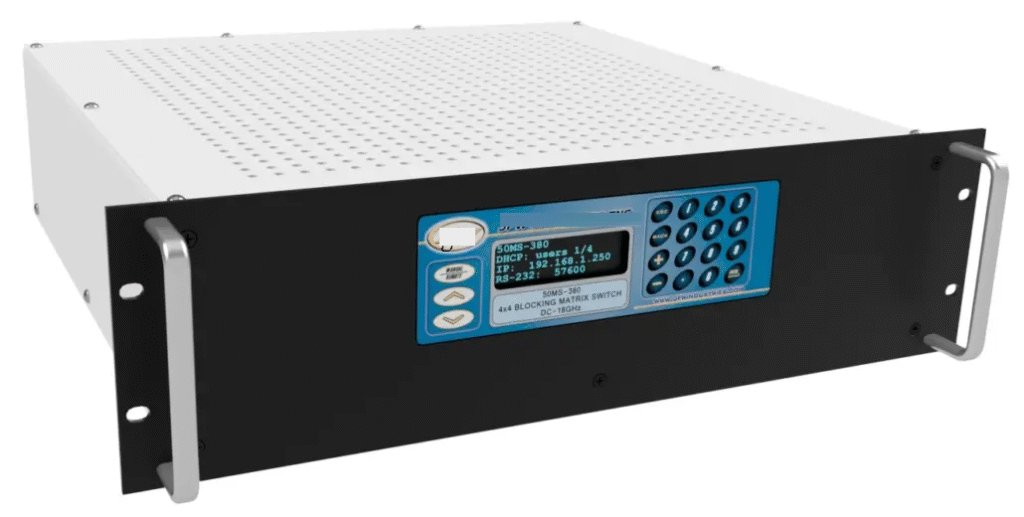
Basic Specification of System
- Configuration : 4×4 Blocking Matrix
- Frequency Range : DC ~ 18 GHz
- RF Input Power : 25W (CW Max)
- Insertion Loss : 0.4dB @ +25°C
- Impedance : 50 Ohms Nominal
- Communication : Ethernet, RS232, RS485 (Expandable)
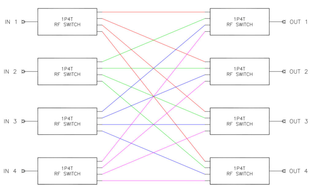
Conceptual Diagram of 4×4 RF Switch Matrix
This diagram shows a conceptual 4×4 RF switch matrix using 1P4T switches, where any of the four inputs can be routed to any of the four outputs. Color-coded lines represent possible RF signal paths between inputs and outputs.
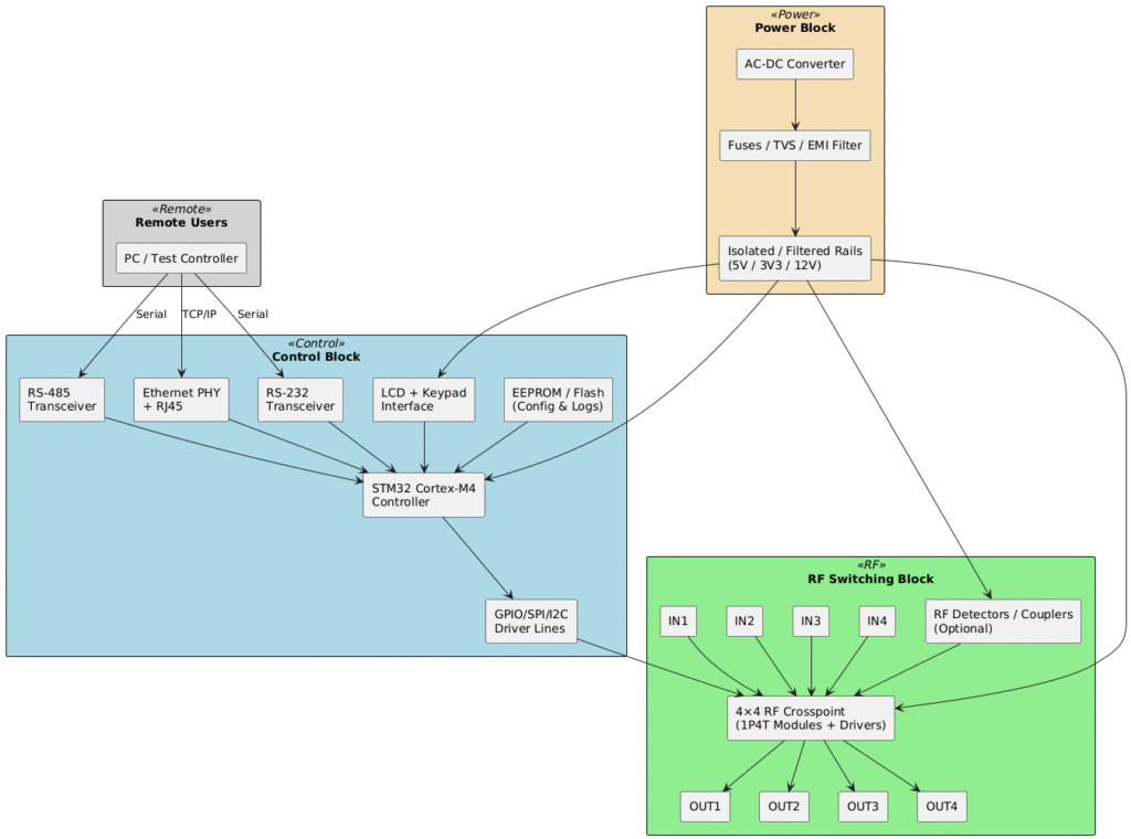
Block Diagram Of Entire System
This system block diagram shows the RF Switch Matrix architecture, including remote user interfaces, control block, RF switching block, and power block. It illustrates how RS-232, RS-485, and Ethernet connect to an STM32 controller, which drives the 4×4 RF crosspoint and associated power distribution.
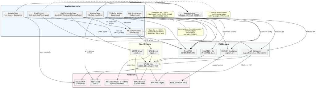
Firmware Architecture Diagram
This architecture diagram illustrates the software and hardware layers of the STM32F439ZI-based RF Switch Matrix, showing interactions between application tasks, middleware, hardware drivers, and connected peripherals. It highlights how network, CLI, UI, and RF switching functions are coordinated via FreeRTOS and HAL to enable flexible remote control and monitoring.
Note: To view high quality image, use plantuml code in repository to any plantuml editor.
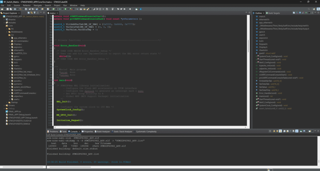
Firmware Build
Screen shot of firmware built with STM32CubeIDE
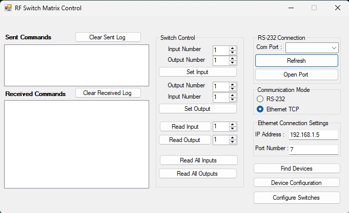
PC GUI
Screen shot of PC GUI app build with Visual Studio 2022
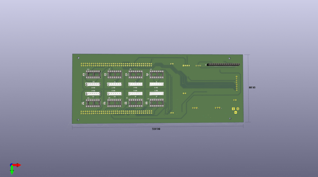
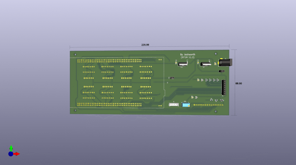
Hardware
Front and back view of board which is designed in Kicad
Conclusion
All the source code, including firmware, drivers, and documentation for this RF Switch Matrix project, is available on GitHub.
Follow the link below to explore, download, or contribute to the repository, and if you have any questions, feel free to leave a comment.